Here
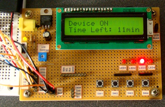
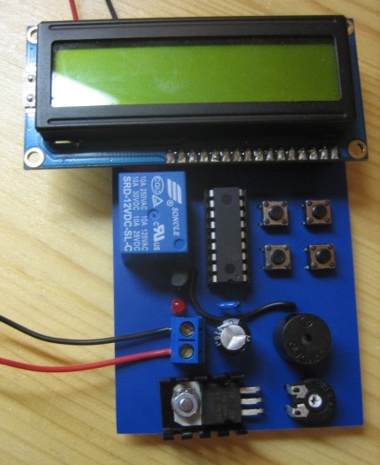
is 0 to 99 minutes relay timer using PIC16F628 microcontroller and 16
character LCD display. The microcontroller is PIC16F628A running at 4.0
MHz clock using an external crystal. An HD44780 based 16×2 character
LCD is the main display unit of the project where you can watch and set
the timer duration using tact switch inputs. There are three tact
switches connected to RB0 (Start/Stop), RB1 (Unit), and RB2 (Ten) pins.
You can select the timer interval from 0-99 min using Unit and Ten
minute switches. The Start/Stop switch is for toggling the timer ON and
OFF. When the timer gets ON, a logic high signal appears on the RA3
pin, which can be used to switch on a Relay. The circuit diagram of
this project is described below.
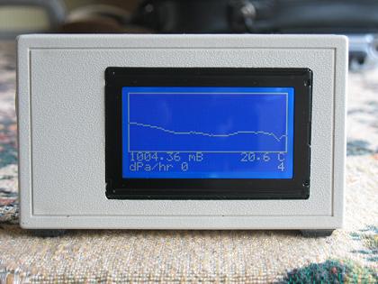
Here's
a digital barometer that uses Atmega8 microcontroller and graphical LCD
display. This project uses SCP barometer pressure sensor graphical LCD
display connected to Atmega8 microcontroller. Graphical LCD displays
latest 128 readings while one reading occur once in 20 minutes. You can
see information of about two last days. Provided C source code can be
customized to your liking.
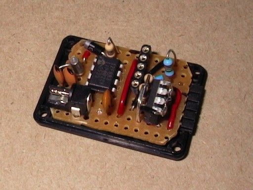
This
project uses a Microchip PIC microcontroller, a serial EEPROM and a
thermistor to create a temperature recorder.
The temperature is measured and stored at user programmable intervals;
this can be from 1 second to 256 seconds. The time interval is set by
programming it and the start time into the EEPROM.
Most of the time the PIC will be asleep and the EEPROM IC is inactive.
This gives a very low current consumption of approximately 50 uA or
about 1 mAh per day.
The EEPROM used is 32kBytes which can store up to 32,000 measurements.
This could be one measurement every 30 seconds for 11 days for example.
The combination of thermistor and analogue circuit gives a range of
between about -40 °C and +100 °C although the linear range is between
about -10 °C and +40 °C.
A
bootloader enables download of hex-files directly into the flash-memory
of a PIC or other microcontroller. The bootloader receives the user
program via the PIC's UART and writes it directly to the program memory
(self programming). This feature greatly speeds up the development
process, because the chip remains in the target circuit and need not be
moved between the target circuit and the programmer.
When no bootloader is installed, all memory in the PIC can be utilized
for user programs. That is 4 K for the 16F873 (0x000 to 0xFFF).
Installing a bootloader means, that some part of the memory is occupied
by the bootloader. The user can download his program into the remaining
memory space. The bootloader in figure 1 occupy 256 words (0xF00 to
0xFFF), that is 6 % of the memory in a 16F873. The disadvantage of
loosing 6 % memory is little compared to the advantage of fast program
download and more friendly development routines.
We
love to read emails from our visitors, Please let us know by clicking
here if you find any kind of bug/error in our site. We will fix it as
soon as possible.
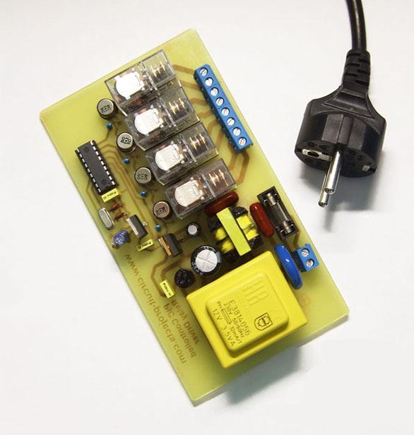
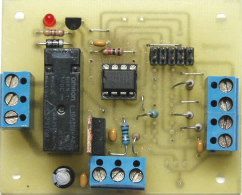
PIC Controlled Relay Driver
This circuit is a relay driver that is based on a PIC16F84A
microcontroller. The board includes four relays so this lets us to
control four distinct electrical devices. The controlled device may be
a heater, a lamp, a computer or a motor. To use this board in the
industrial area, the supply part is designed more attentively. To
minimize the effects of the ac line noises, a 1:1 line filter
transformer is used.
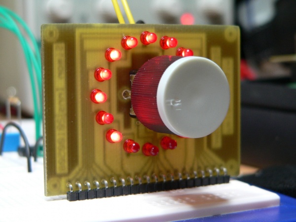
Rotary
encoders are very versatile input devices for microcontroller projects.
They are like potentiometers expect of digital nature and unlike
analogue potentiometers they never wear down. Rotary encoders not only
provide 360 degrees of rotational freedom they also allow digital
positioning information to be gained without the use of analogue to
digital converters (ADCs). When using rotational encoders in projects
it's possible to use the same encoder to represent a number of
different input types, however this requires some form of feedback
display to let the user know what information he is inputting and the
'position' of the encoder. The project is based around a 24 position
rotary encoder, 16 LEDs arranged in a circle around the encoder, an
A6276 16 LED serial driver IC and the PIC182550 microcontroller. A
rotary encoder has 3 pins usually called A, B and C. The C pin (which
is normally the centre pin) should be grounded and both A and B should
be connected to the microcontroller with individual pull-up resistors
on each input. In this project I used RB4 and RB5 on the PIC to connect
the encoder; this has 2 advantages, firstly you can use the PORTB
internal weak pull-up (which means you do not need external resistors)
and also the PIC provides an 'interrupt-on-change' which can be used to
monitor the encoder.
For
a long time I needed a good programmer pussy, even if it is
programming, so from time to time the application gets where it is
used. So I decided to build the programmer. I chose between a couple of
projects from different authors, but eventually won PICkit2. Microchip
released the schema directly in the user manual for the programmer. On
the Internet there are multiple versions of the programmer, it's
usually cropped version of the log analyzer features, UART terminal,
etc., 12V inverter is a modified version of it and control the MOSFETs,
unlike bipolar transistors used in the original design. And it also
showed that becomes due to the switching inductance feta leave.
Finally, I chose to use the original scheme, although it is quite
complicated and the parts used in our country can not normally buy, but
my problems with finding parts easily solved. I bought a transistor,
the 16F2550 PIC and a few other things, resistors and fry the rest I
bought from "us". The price is pretty high, unfortunately, moving it
around and 600CZK, the main prize and two processor makes the EEPROM.
Below we describe the involvement and put into operation.
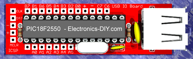
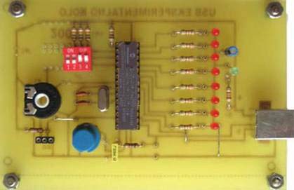
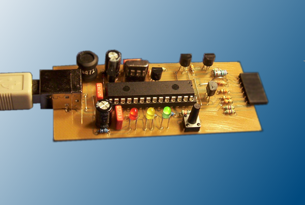
USB
Input / Output Board is a spectacular little development board /
parallel port replacement featuring PIC18F2455 / PIC18F2550
microcontroller. USB IO Board is compatibile with Windows / Mac OSX /
Linux computers. When attached to Windows IO board will show up as
RS232 COM port. You can control 16 individual microcontroller I/O pins
by sending simple serial commands. USB Input / Output Board is
self-powered by USB port and can provide up to 500mA for electronic
projects.
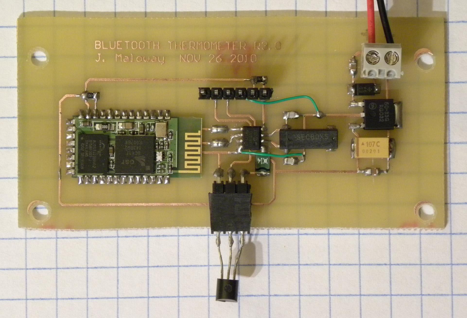
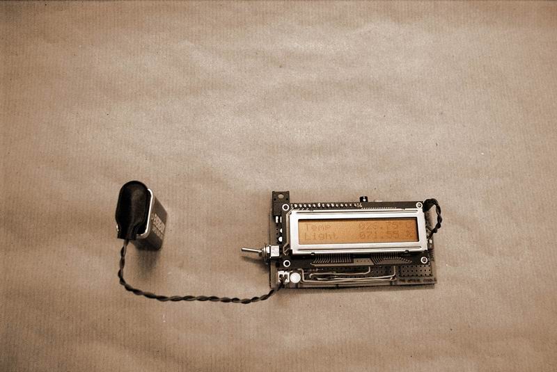
One
morning I woke up and wanted to know what the temperature outside was,
and instead of running over to Home Depot and picking up a $2.00 glass
thermometer, I decided to build my own wireless temperature sensor. At
the heart of the board is a PIC12F675 microcontroller in an SO8
package. The right-hand side of the board houses the linear power
supply (LP2950), bottom-center is the DS18B20 1-Wire temperature
sensor, and out in left-field you can see the Sure TTL Bluetooth
Module.
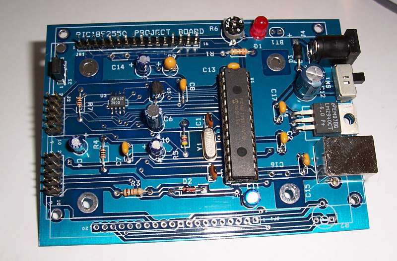
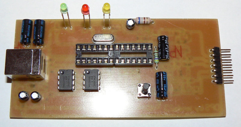
The
new PIC18F2550 Project Board was designed as the development platform
for student projects. The board platform is suitable for developing the
microcontroller based instrumentation. Students may build the signal
conditioning board, plugs it to PIC project board, develops the code
and programs it with loader cable easily.
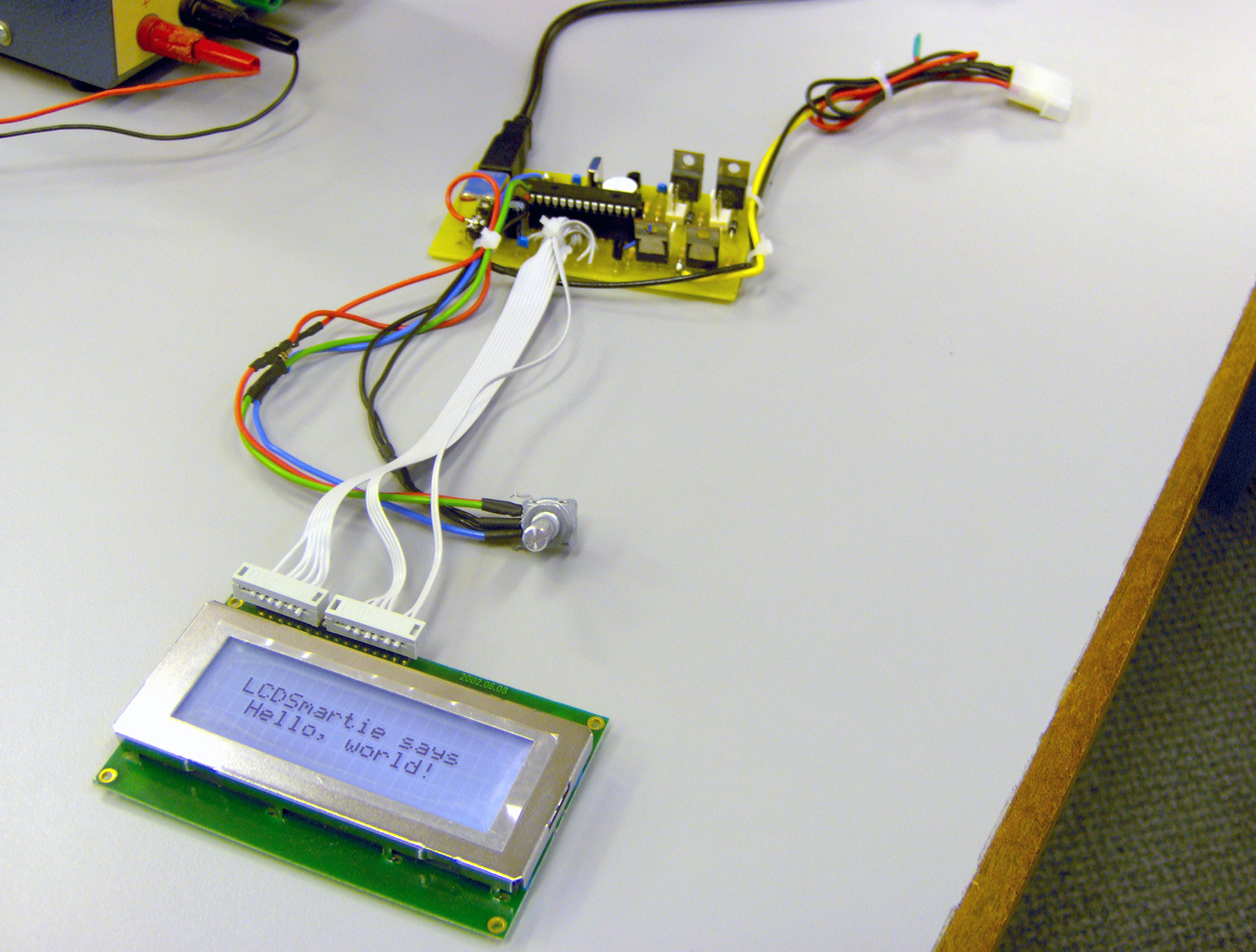
If
you like PC modding this is cool project for you.this is an USB
interface for alphanumeric LCD display like 4x20 which can be
controlled with LCDSmartie program.USB interface is implemented by
using PIC18F2550 microcontroller. Using USB LCD module you can view
many types of information taken from PC like temperatures, time/date,
MP3 song titles, view emails, RSS feeds all that LCDSmartie or other
program supports.
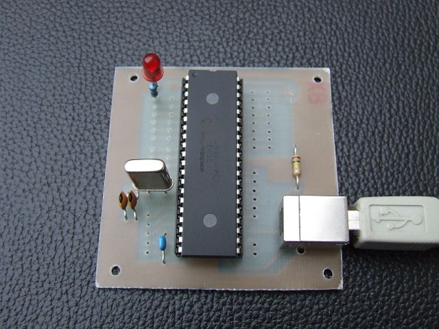
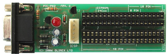
Pinguino
is an Arduino-like board based on a PIC Microcontroller. The goal of
this project is to build an integrated IDE easy to use on LINUX,
WINDOWS and MAC OS X. This is a simple 40 pin PIC development board as
described in RadCom for November 2009. It is designed for a PIC18F4550,
but it will work with other 40 pin PICs like the PIC16F877A. It has no
bells & whistles attached. No buttons, LED, LCD ICSP etc. All of
the PIC pins are easily accessible so that you can add any features you
need. This board has been tested with the Vasco PUF and the Pinguino
USB bootloaders.
This
project uses the 12F675, it was chosen because of its low cost, A/D
convertor and flash memory. This security system was designed to be
used in a simple installation with just a hidden switch and not a
keyboard. There are several features such as a battery monitor built
into the code that also make it good for remote locations just run off
a battery. Also all the delays and and other parameters are put into
flash memory just by using a visual basic program and the serial port
of a PC.
This
is a digital thermometer based on USB PIC16C745 microcontroller from
Microchip and DS1820 sensor from Dallas Semiconductor. Temperature
readings are sent over USB port in HIDCOMM USB mode to VB6 program on a
PC. Hex program and sample Visual Basic 6 application is included.
Circuit
measures the temperature and ambient brightness of the surrounding
environment at the location it is placed. The data from the ADC is the
calculated and displayed on the LCD. The main CPU unit on board the
device is the PIC16F873.
Manji
broj proizvođača proizvodi IC kola za USB podršku. Najpoznatiji su:
Cypress Semiconductor, FTDI, Philips i drugi. Microchip je 2000 godine
proizveo mikrokontrolere PIC16C745 i PIC16C675 koji su imali podršku za
USB komunikaciju i tako se pridružio ostalim proizvođačima. Ovi
mikrokontroleri podržavaju USB 1.1 standarad, odnosno USB sa brzinama
rada do 1.5 MBs. Nova serija Microchip-ovih mikrokontrolera urađenja u
flash tehnologiji PIC18F2445/2550/4455/4550 je podržala USB 2.0
standrad. Ovo su moćni mikrokontroleri sa brzinama takta i preko 40Mhz
i veličinom programske memorije od 32K reči. O stanadardima za USB
možete na sajtu http://www.usb.org.
Upravo na ovim mikrokontrolerima
urađen je interfejs sa USB komunikacijom.
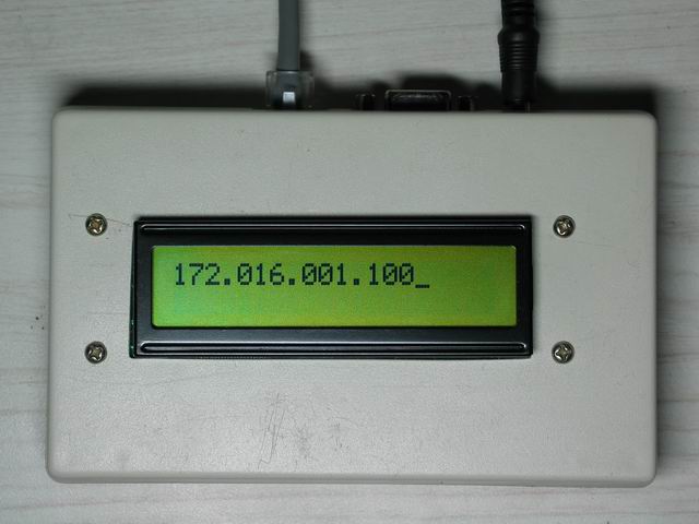
When
the device is connected to the computer, a Virtual COM Port (VCP) will
be created. This is shown at the Device Manager Window under Ports(COM
& LPT). In this case, COM5 was created when the PIC18F4550 was
attached to the USB Port. It may be interesting to note that if you
plug in your PIC in different USB ports, the VCP created will be
different.
The
quickest way to display something is probably sending the data to the
computer to be displayed on the monitor. One of the ways to do this is
to use the USART module on board the PIC Microcontroller by making use
of the pins RC6 and RC7 which is also the TX and RX pins respectively
when the SPEN bit on the RCSTA register is set.
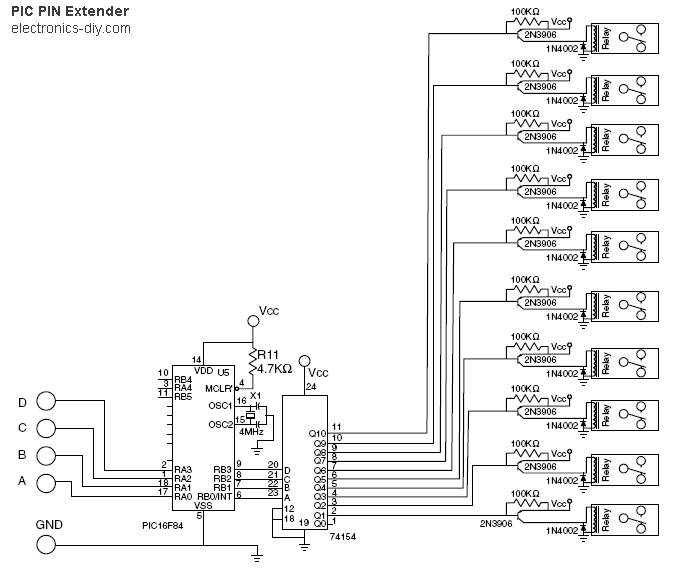
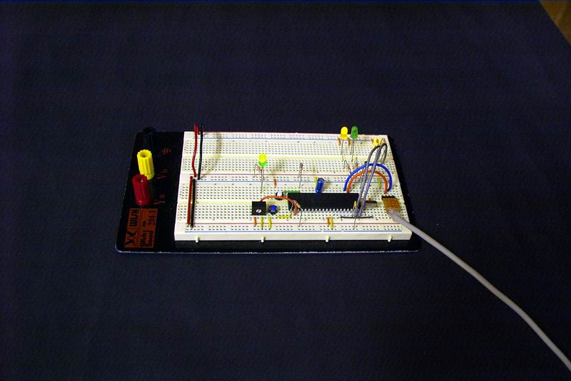
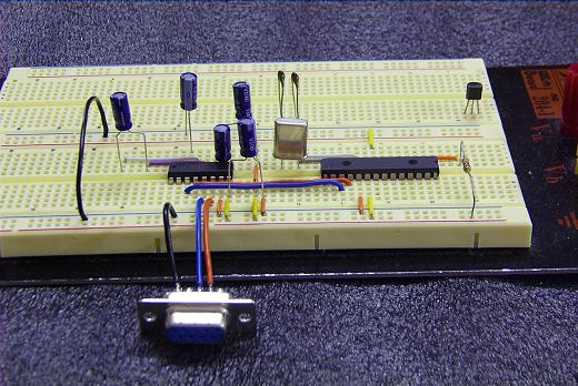
This
circuit based around 74LS154 will extend PIC / AVR microcontroller
output PINs from 4 to up to 16. It can also be used for extending
parallel port output pins.
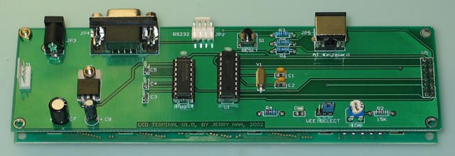
The
LCD Terminal just like a normal terminal, it can connect to any host
via RS-232 serial cable. A PC keyboard must connect to it as the input
device and what ever you type will send to host via RS-232 and display
on a 40x4 LCD.
Data receive from host can also display on the LCD unit.
You can use this device as any Unix/Linux machine's console.
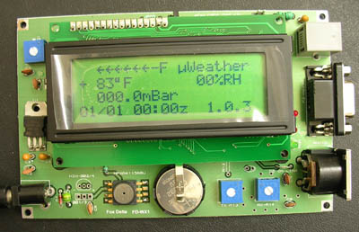
Weather
Station is PIC16F877A based and has a 4x20 LCD, a data logger output
and accepts 1Wire wind instrument. It has a built-in APRS TNC. Connect
it to your portable rig thru a DIN5 connector and you have a true
portable weather station.
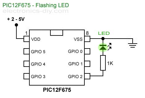
Simple
little circuit for testing PIC12F675 microcontroller. When you start
learning a programming language like C++, Visual Basic or any other
language your first step is to write a program that displays "Hello
World" on a computer's monitor. When you start learning how to program
PIC microcontrollers an equivalent to that is blinking a LED.
Serial
LCD/VFD Controller is a HD44870 based LCD/VFD controller via RS-232.
The control command is compatible with Matrix-Orbital's LCD module.
So, you can use any MO friendly software to control this baby such as
LCDC.
PICNIC
is a project to add 10BaseT Ethernet controller to PIC17F877, and it
can run as an network-enable device.
This project is based on tristate's PICNIC product. And I just change
the temperature sensor's circuits to improve the precision on A/D
convert and add another Temp-Sensor channel.
This
project is based on ideas from Rickard's electronic projects page and
David B. Thomas VCR Pong. However, I have developed the simplicity even
further, eliminating most of the external components. Using
microcontrollers with internal 4MHz clock generator there is no need
for the xtal. The 12f675 part also operates on wide voltage range, and
the regulator can be removed.
For game controller, I plan on using the old Commodore 64 style
paddless. They include firing buttons, which I plan on using as power
switch and game reset. 16F675 has a low power sleep mode with 1nA
current consumption, so I plan on using that to switch off.
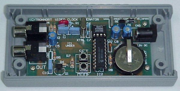
Perfect
low cost solution for: * New video security
installations * SSTV transmitters * Amateur video * Existing installed
security installations * Scientific experimentation monitoring * and
any other application that needs the time and date recorded on an
image!
If
you need an UV LED timer, or a timer for any other purpose you may be
interested in the UV LED Controller that was constructed using a PIC
16F628A Microcontroller. There is a schematic and code available
however the original project was not documented in English. Have a look
at the Google translation that did a decent job of translating this
one.

The
new PIC18F2550 Project Board was designed as the development platform
for student projects. The board features MCU: PIC18F2550 with external
xtal, ADC: one channel 0-2.5V sigma-delta converter, Linear Technology
LTC2400/LTC2420, 6-channal 10-bit ADC 0-5V, Display: Two connectors for
text LCD or GLCD, USB: onchip USB port with type B connector, Power
supply: onboard low dropout regulator, rechargeable battery, Code
programming: 10-pin header for In Circuit Loader. The board platform is
suitable for developing the microcontroller based instrumentation.
Students may build the signal conditioning board, plugs it to PIC
project board, develops the code and programs it with loader cable
easily.
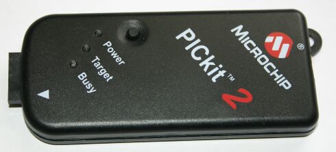
PICKit
2 Starter Kit is the low cost ICSP programmer for Flash PICs with USB
interface introduced recently by Microchip. Only subset of PIC
microcontrollers is supported, but the list is including all the recent
devices from PIC16 and PIC18 families. The software upgrades are free
and Microchip updates them in timely fashion. Even more, the source
code and schematic are freely available.
JDM2
PIC 18F Programmer is programmer based on JDM design which takes all
necessary signals and power supply from RS232 serial port. It supports
8, 18, 28 and 40 pin PIC microcontrollers which allow serial
programming and I2C EEPROM memories. Programmer comes with ICSP cable
for direct connection to prototype boards. The supported devices depend
on the current version of ICPROG software. JDM2 programmer is supported
by ICProg, PICPgm and WinPic PIC programming software
.
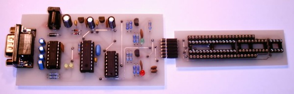
The
PIC programmer project presented here is intended to be used by more
experienced developers who already have access to a simple PIC
programmer, because the programmer hardware is built around one
16F627(A) or 16F628(A) microcontroller that has to be preprogrammed
with firmware. The presented solution uses PC's serial port for
reliable communication between the programming software and
'intelligent' PIC programmer hardware.
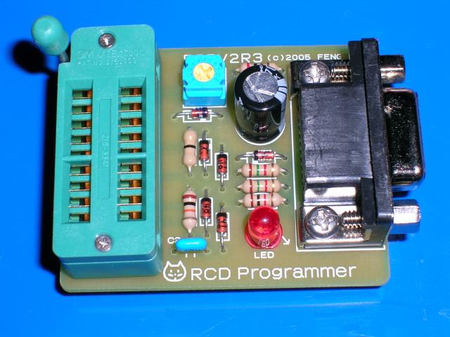
I
believe that the "JDM Programmer" is cheap and very useful PIC
Programmer. However, since "JDM Programmer" cannot control VDD, the
algorithm "VPP before VDD" is inapplicable. Programming to the latest
device from this reason may go wrong when using CONFIG settings as
"Internal oscillator" "MCLR OFF". These devices are given power from
the "JDM programmer",and execute program code. An error may come out by
verification, or it may become impossible erasure and become impossible
re-programming . In order to solve this problem, I designed a
programmer based on the "JDM programmer." Since this programmer was
made of resistors, capacitors, and diodes, I named this the "RCD
Programmer." "Hardware settings" of IC-Prog are the same as the "JDM
programmer."
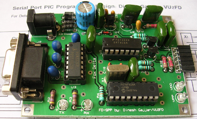
PIC
Programmer is an essential tool if you wish to learn or build projects
with Microchip PIC Micro Processors. This serial programmer is for
those who do not have a Parallel Port on their PC. Programmer may be
used with PIC PROGRAMMER Professional Serial programming software from
Oshosoft or other serial programming software.
This
is a PICkit 2 MPLAB compatibile Programmer. It is a low-cost
development tool with an easy to use interface for programming and
debugging Microchip’s Flash families of microcontrollers. The full
featured Windows programming interface supports baseline (PIC10F,
PIC12F5xx, PIC16F5xx), midrange (PIC12F6xx, PIC16F), PIC18F, PIC24,
dsPIC30, dsPIC33, and PIC32 families of 8-bit, 16-bit, and 32-bit
microcontrollers, and many Microchip Serial EEPROM products. With
Microchip’s powerful MPLAB Integrated Development Environment
(IDE) the PICkit 2 enables in-circuit debugging on most PIC
microcontrollers. In-Circuit-Debugging runs, halts and single steps the
program while the PIC microcontroller is embedded in the application
. When halted at a breakpoint, the file registers can be examined and
modified.
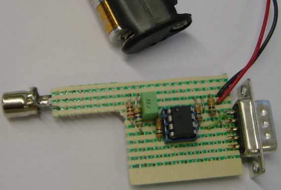
Circuit
is very simple. The generator uses a PIC12F629 microcontroller with
clock frequency set by an external RC. Output frequency can be set
trimmer P1 in the range of about 2 to 170 Hz. Oscillator frequency can
be adjusted if you change C1 capacitance. Pulses are generated with a
period of 200 Tcy. All pulses are of equal length. Output frequency is
800 times lower than the frequency of the oscillator.
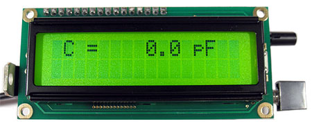
Build
your own LC Meter and start making your own coils and inductors. This
LC Meter allows to measure incredibly small inductances making it
perfect tool for making all types of RF coils. LC Meter can measure
inductances starting from 10nH - 1000nH, 1uH - 1000uH, 1mH - 100mH and
capacitances from 0.1pF up to 900nF. The circuit includes an auto
ranging and "Zero Out" function to make sure the readings are as
accurate as possible ...
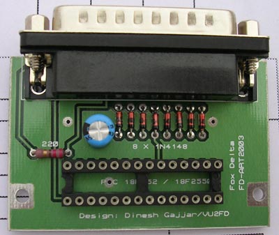
Developed specifically for programming of PIC 18F2550 micro controllers, this parallel port, no-power, programmer is the smallest of all programmers ever built. A DB25 Male Connector, one capacitor and a resistor makes this Port Powered programmer. Programmer takes its power from Parall
I'm glad to have found this post as its such an interesting one! I am always on the lookout for quality posts and articles so i suppose im lucky to have found this! I hope you will be adding more in the future...
ReplyDeleteAlarm System Monitoring
VERY NICE CIRCUITS, THESE I THINK ARE SUITABLE FOR EDUCATION FOR BASICS OF MICRO-CONTROLLERS.
ReplyDeleteI want to say that there is no need to go through signing to my account to leave a comment. It's a blog.
ReplyDeleteI suggest you leave it commenting to earn more simplicity for saying something.
DEAR SIR
ReplyDeletePLS TELL ME HOW I CAN CONNECT THE INCREMENTAL ENCODER WITH MCU 89S52 THE ENCODER PPR RATED 510
viveksharmanitu@gmail.com