Digital clock design has been the interest of many embedded system engineers today, i decided to write this article to share the knowledge of how to design DIY digital clock when the 14yrs old Ahmed Mohamed was arrested for designing a digital clock.
For this projects i have decided to use one of the most common PIC microcontroller from microchip technology PIC16F877A and DS1307 RTC by maxim integrated.
Digital clock using ds1307 and pic16f877a microcontroller is designed in this project. Digital clock using ds1307 displays time and date on LCD. PIC16F877A microcontroller is used to design digital clock. I2C communication protocol is used to read time and date from digital clock ds1307. PIC16F877A microcontroller is interfaced with LCD to display time and date. Digital clock ds1307 use I2C serial communication proctol to send data to microcontroller. pic16f877a microcontroller receives data from ds1307 through I2C serial communication protocol.
Digital clock DS1307
DS1307 is an integrated circuit based
real time clock. It counts minutes, seconds, hours, date of month, days
and years. It also have functionality to include leap year compensation
up to 2100. It is binary coded decimal clock (BCD). This clock operates
in either in 12 hour or 24 hour format. Indication of Am and Pm can also
be included on LCD display through programming. It also have automatic
power failure circuit. Automatic power failure circuit detects power
failure and switch to 3 volt battery to keep record of time. It have
battery back up. Battery back up is used to keep record of time in case
of main power failure. It have 56 bytes non-volatile RAM for data
storage. DS1307 use two wire serial communication I2C. It consumes very
less power and current in the order of 500nA. It can operate in harsh
temperature environment in the range of -40ºC to +85°C.
Digital clock DS1307 Pin configuration
It is 8-pin DIP IC. Pin configuration of DS1307 is given below:
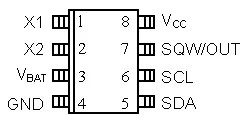
Description of each pin is given below:
- SQW/OUT : Square wave and output driver pin
- SCL: Serial clock used for I2C communication
- SDA : Serial data pin for I2C serial communication
- GND: Ground pin of power supply is connected with this pin
- VBAT : It is 3 volt back up battery. It is use in case of main power failure
- X1 and X2 : 32.768 crystal connects with these pins
- Vcc : Main power supply connects with this pin
In I2C serial communication, one device acts as a slave and other device
acts as a master. Slave only respond to instructions of master. Slave
can not give instructions to master. Digital clock DS1307 acts as a
slave and respond to instructions of microcontroller. Built in register
in ds1307 is used to respond to instructions of microcontroller. As
shown in above circuit diagram, SCL pin of ds1307 is connected to SCL
pin of microcontroller. It is used to synchronize serial data on serial
wire. SCL stands for serial clock input. SDA stands for serial data
input/output. SDA pin of ds1307 is connected with SDA pin of
microcontroller. SDA is used as a serial data input or output for 2 wire
serial communication. SDA pin of ds1307 is open drain that is why its
required external pull up resistor as shown in figure above. Standard
32.876KHz quartz crystal is used with real time clock ds1307.
Circuit diagram of digital clock ds1307 using pic microcontroller
Circuit
diagram of digital clock ds1307 using pic mirocontroller is given
below. DS1307 real time clock is interfaced with PIC16F877A
microcontroller. Instructions for interfacing real time clocl ds130 is
given. 3 volt battery is used as back up which is used in case of main
power supply faliure.PIC16F877A microcontroller fetch time and date
values from DS1307 real time clock. After doing some calculations
through programming, PIC16F877A microcontroller displays time and date
on LCD.

Code of digital clock DS1307 using pic microcontroller
Code for real time clock using DS1307 and pic microcontroller is written
using Mikro C pro compiler. Necessary comments are also made in code
for your understanding.
//written at Pulsetronics Technology lab
// LCD module connections
sbit LCD_RS at RB6_bit;
sbit LCD_EN at RB4_bit;
sbit LCD_D4 at RB3_bit;
sbit LCD_D5 at RB2_bit;
sbit LCD_D6 at RB1_bit;
sbit LCD_D7 at RB0_bit;
sbit LCD_RS_Direction at TRISB6_bit;
sbit LCD_EN_Direction at TRISB4_bit;
sbit LCD_D4_Direction at TRISB3_bit;
sbit LCD_D5_Direction at TRISB2_bit;
sbit LCD_D6_Direction at TRISB1_bit;
sbit LCD_D7_Direction at TRISB0_bit;
// End LCD module connections
unsigned short read_ds1307(unsigned short address)
{
unsigned short r_data;
I2C1_Start();
I2C1_Wr(0xD0); //address 0x68 followed by direction bit (0 for write, 1 for read) 0x68 followed by 0 --> 0xD0
I2C1_Wr(address);
I2C1_Repeated_Start();
I2C1_Wr(0xD1); //0x68 followed by 1 --> 0xD1
r_data=I2C1_Rd(0);
I2C1_Stop();
return(r_data);
}
void write_ds1307(unsigned short address,unsigned short w_data)
{
I2C1_Start(); // issue I2C start signal
//address 0x68 followed by direction bit (0 for write, 1 for read) 0x68 followed by 0 --> 0xD0
I2C1_Wr(0xD0); // send byte via I2C (device address + W)
I2C1_Wr(address); // send byte (address of DS1307 location)
I2C1_Wr(w_data); // send data (data to be written)
I2C1_Stop(); // issue I2C stop signal
}
unsigned char BCD2UpperCh(unsigned char bcd)
{
return ((bcd >> 4) + '0');
}
unsigned char BCD2LowerCh(unsigned char bcd)
{
return ((bcd & 0x0F) + '0');
}
int Binary2BCD(int a)
{
int t1, t2;
t1 = a%10;
t1 = t1 & 0x0F;
a = a/10;
t2 = a%10;
t2 = 0x0F & t2;
t2 = t2 << 4;
t2 = 0xF0 & t2;
t1 = t1 | t2;
return t1;
}
int BCD2Binary(int a)
{
int r,t;
t = a & 0x0F;
r = t;
a = 0xF0 & a;
t = a >> 4;
t = 0x0F & t;
r = t*10 + r;
return r;
}
int second;
int minute;
int hour;
int hr;
int day;
int dday;
int month;
int year;
int ap;
unsigned short set_count = 0;
short set;
char time[] = "00:00:00 PM";
char date[] = "00-00-00";
void main()
{
I2C1_Init(100000); //DS1307 I2C is running at 100KHz
CMCON = 0x07; // To turn off comparators
ADCON1 = 0x06; // To turn off analog to digital converters
// TRISC = 0X00; TRISE =0X00 ;
TRISA = 0x07;
PORTA = 0x00;
TRISB = 0; PORTB =0;
Lcd_Init(); // Initialize LCD
Lcd_Cmd(_LCD_CLEAR); // Clear display
Lcd_Cmd(_LCD_CURSOR_OFF); // Cursor off
Lcd_out(1,1,"Time:");
Lcd_out(2,1,"Date:");
do
{
set = 0;
if(PORTA.F0 == 0)
{
Delay_ms(100);
if(PORTA.F0 == 0)
{
set_count++;
if(set_count >= 7)
{
set_count = 0;
}
}
}
if(set_count)
{
if(PORTA.F1 == 0)
{
Delay_ms(100);
if(PORTA.F1 == 0)
set = 1;
}
if(PORTA.F2 == 0)
{
Delay_ms(100);
if(PORTA.F2 == 0)
set = -1;
}
if(set_count && set)
{
switch(set_count)
{
case 1:
hour = BCD2Binary(hour);
hour = hour + set;
hour = Binary2BCD(hour);
if((hour & 0x1F) >= 0x13)
{
hour = hour & 0b11100001;
hour = hour ^ 0x20;
}
else if((hour & 0x1F) <= 0x00)
{
hour = hour | 0b00010010;
hour = hour ^ 0x20;
}
write_ds1307(2, hour); //write hour
break;
case 2:
minute = BCD2Binary(minute);
minute = minute + set;
if(minute >= 60)
minute = 0;
if(minute < 0)
minute = 59;
minute = Binary2BCD(minute);
write_ds1307(1, minute); //write min
break;
case 3:
if(abs(set))
write_ds1307(0,0x00); //Reset second to 0 sec. and start Oscillator
break;
case 4:
day = BCD2Binary(day);
day = day + set;
day = Binary2BCD(day);
if(day >= 0x32)
day = 1;
if(day <= 0)
day = 0x31;
write_ds1307(4, day); // write date 17
break;
case 5:
month = BCD2Binary(month);
month = month + set;
month = Binary2BCD(month);
if(month > 0x12)
month = 1;
if(month <= 0)
month = 0x12;
write_ds1307(5,month); // write month 6 June
break;
case 6:
year = BCD2Binary(year);
year = year + set;
year = Binary2BCD(year);
if(year <= -1)
year = 0x99;
if(year >= 0x50)
year = 0;
write_ds1307(6, year); // write year
break;
}
}
}
second = read_ds1307(0);
minute = read_ds1307(1);
hour = read_ds1307(2) | 0x40 ;
hr = hour & 0b00011111;
ap = hour & 0b00100000;
dday = read_ds1307(3);
day = read_ds1307(4);
month = read_ds1307(5);
year = read_ds1307(6);
time[0] = BCD2UpperCh(hr);
time[1] = BCD2LowerCh(hr);
time[3] = BCD2UpperCh(minute);
time[4] = BCD2LowerCh(minute);
time[6] = BCD2UpperCh(second);
time[7] = BCD2LowerCh(second);
date[0] = BCD2UpperCh(day);
date[1] = BCD2LowerCh(day);
date[3] = BCD2UpperCh(month);
date[4] = BCD2LowerCh(month);
date[6] = BCD2UpperCh(year);
date[7] = BCD2LowerCh(year);
if(ap)
{
time[9] = 'P';
time[10] = 'M';
}
else
{
time[9] = 'A';
time[10] = 'M';
}
Lcd_out(1, 6, time);
Lcd_out(2, 6, date);
Delay_ms(100);
}while(1);
}
No comments:
Post a Comment