As a beginner it is advisable to start writing codes for microcontroller step by step, That's why we decided to write an article on blinking Light Emitting Diodes(LCD)

In this tutorial we will learn How to Blink an LED with PIC Microcontroller using MPAB XC8 Compiler. Recently Microchip released a series of development tools including MPLAB X IDE and MPAB XC Compilers. MPLAB X IDE is a software that runs on a computer intended to develop applications for Microchip’s Microcontrollers and Digital Signal Controllers. It can be used with Windows, Mac and Linux Operating Systems. It is called an Integrated Development Environment as it provides comprehensive facilities to the developers. Unlike previous versions of MPLAB, MPLAB X IDE is based on open source NetBeans IDE by Oracle.
MPLAB XC Compilers are general solutions for all Microchip PIC Microcontrollers and it can be used for any Project. It replaces all MPLAB C and Hi-Tech C compilers. Microchip recommends every developers to use MPLAB XC Compilers. These compilers integrates with MPLAB X IDE to provide full graphics front end.
Note: I am using a Windows computer. If you are using OSX or Linux there may be slight differences to the exact procedure.
In this example project we will blink an LED using PIC 16F877A Microcontroller. For that we will use MPLAB X IDE and MPLAB XC8 Compiler. You can download MPLAB X IDE and XC8 Compiler from the respective pages.
You should install Java before installing MPLAB X.
Be sure to install the Free version. You can try the Pro version for a limited time, but I don't recommend it for one reason: When your trial expires, you may find you can no longer fit some of your projects within the memory of your device because your binaries are not being optimized anymore!
If you think you will want to use XC8 from the command line, make sure to check the option to update your system's PATH variable.

Under Categories, select Microchip Embedded. Under Projects, select Standalone Project. You can also do other things such as import an MPLAB v8 project or start a Library Project. However, the basic starting point is the Standalone Project. When done, click Next.

We now must tell MPLAB X what specific device we are programming. In this guide I am assuming a PIC16F690. It can be found in the Midrange family. Once you have selected the correct device, click Next.
 Select the PIC microcontroller you want to use, in the
next step you will be asked if you are using a debug header. This guide
assumes you don't have one, so select "None".
Select the PIC microcontroller you want to use, in the
next step you will be asked if you are using a debug header. This guide
assumes you don't have one, so select "None".

The next step is to tell MPLAB X which programming/debugging tool we are using. Select whichever programming tool you have. However, this guide will assume you are using a PICkit2 or PICkit3.

The next step is to tell MPLAB X which compiler we will use. If you have installed XC8 correctly, it will show up in the list with a green circle beside it. Click it then click Next.

The next window involves giving our project a name and telling MPLAB where to save it. Type a name for your project. I will use BeginnerGuide. Next, choose a Project Location. I always save my projects in C:\PIC. You can choose whatever suits you. The ProjectFolder field will be automatically populated. You do not need to change it. When you are done, click Finish.
We now have a new project ready to go. Your main window should look like the image below

Now we must add some source code to our project to test it out. In the Projects tab right-click Source Files. Select New>Empty File...

Type main.c for File Name. If you wish to keep your source files separate from the other project files, you can type a name in the Folder field. "src" is a common choice. I will leave it blank and place the file in the main project directory. When you are done, click Finish.
In the main window you will now see the contents of main.c. It is empty! Let's type in some code so we can test the compiler. Copy the following code into main.c
#include <xc.h>
int main()
{
NOP();
}
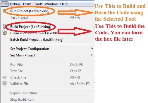
We are now ready to compile our code. In the toolbar, click Build Project.

Build is the hammer icon.
If everything is installed correctly, you will see a Build Successful
message in the Output window. If you are getting errors, double check
your steps. Check the Output window for hints as to what is wrong.


In this tutorial we will learn How to Blink an LED with PIC Microcontroller using MPAB XC8 Compiler. Recently Microchip released a series of development tools including MPLAB X IDE and MPAB XC Compilers. MPLAB X IDE is a software that runs on a computer intended to develop applications for Microchip’s Microcontrollers and Digital Signal Controllers. It can be used with Windows, Mac and Linux Operating Systems. It is called an Integrated Development Environment as it provides comprehensive facilities to the developers. Unlike previous versions of MPLAB, MPLAB X IDE is based on open source NetBeans IDE by Oracle.
MPLAB XC Compilers are general solutions for all Microchip PIC Microcontrollers and it can be used for any Project. It replaces all MPLAB C and Hi-Tech C compilers. Microchip recommends every developers to use MPLAB XC Compilers. These compilers integrates with MPLAB X IDE to provide full graphics front end.
Note: I am using a Windows computer. If you are using OSX or Linux there may be slight differences to the exact procedure.
In this example project we will blink an LED using PIC 16F877A Microcontroller. For that we will use MPLAB X IDE and MPLAB XC8 Compiler. You can download MPLAB X IDE and XC8 Compiler from the respective pages.
You should install Java before installing MPLAB X.
Step 1: Installing MPLAB X
The newest version of MPLAB X can be found here. Navigate to the Downloads tab on that page and select the appropriate version for your computer. Download the file and run the installer. It is OK to use default installation options.Step 2: Installing XC8
XC8 can be downloaded here. Click "Downloads" in the left hand menu and select the version of XC8 for your computer. Download the file and run the installer. Once again, default options are OK.Be sure to install the Free version. You can try the Pro version for a limited time, but I don't recommend it for one reason: When your trial expires, you may find you can no longer fit some of your projects within the memory of your device because your binaries are not being optimized anymore!
If you think you will want to use XC8 from the command line, make sure to check the option to update your system's PATH variable.
Step 3: Running MPLAB X
Launch MPLAB X. When the application is ready, click File>New Project. This will launch the New Project window. We will start a new project from scratch. Under Categories, select Microchip Embedded. Under Projects, select Standalone Project. You can also do other things such as import an MPLAB v8 project or start a Library Project. However, the basic starting point is the Standalone Project. When done, click Next.
We now must tell MPLAB X what specific device we are programming. In this guide I am assuming a PIC16F690. It can be found in the Midrange family. Once you have selected the correct device, click Next.
Select the PIC microcontroller you want to use, in the
next step you will be asked if you are using a debug header. This guide
assumes you don't have one, so select "None". The next step is to tell MPLAB X which programming/debugging tool we are using. Select whichever programming tool you have. However, this guide will assume you are using a PICkit2 or PICkit3.
The next step is to tell MPLAB X which compiler we will use. If you have installed XC8 correctly, it will show up in the list with a green circle beside it. Click it then click Next.
The next window involves giving our project a name and telling MPLAB where to save it. Type a name for your project. I will use BeginnerGuide. Next, choose a Project Location. I always save my projects in C:\PIC. You can choose whatever suits you. The ProjectFolder field will be automatically populated. You do not need to change it. When you are done, click Finish.
We now have a new project ready to go. Your main window should look like the image below
Now we must add some source code to our project to test it out. In the Projects tab right-click Source Files. Select New>Empty File...
Type main.c for File Name. If you wish to keep your source files separate from the other project files, you can type a name in the Folder field. "src" is a common choice. I will leave it blank and place the file in the main project directory. When you are done, click Finish.
In the main window you will now see the contents of main.c. It is empty! Let's type in some code so we can test the compiler. Copy the following code into main.c
#include <xc.h>
int main()
{
NOP();
}
We are now ready to compile our code. In the toolbar, click Build Project.
Build is the hammer icon.
MPLAB XC8 Programming
- Input Outputs pins of a PIC Microcontroller is divided into different PORTS containing a group of GPIO (General Purpose Input Output) pins.
- Since PIC 16F877A is an 8-bit microcontroller, each PORT contains 8 Input Output pins.
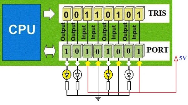
- In 16F Microcontrollers, each port is associated with two registers : TRIS and PORT. Eg : TRISB, PORTB, TRISD, PORTD.
- TRIS stands for Tri-State, it determines the direction of each GPIO pins. Logic 1 at a particular bit of TRIS register makes the corresponding pin Input while Logic 0 at a particular bit makes the corresponding pin Output.
- All Input pins will be in Hi-Impedance state.
- PORT Register is used to Read Data from or Write Data to Input Output pins.
- For an Output pin (TRIS bit is 0), Logic 1 at PORT register makes the corresponding pin Logic High (VDD) and Logic 0 at PORT register makes the corresponding pin Logic Low (VSS).
- Since PIC 16F877A is a 5V device, VDD = 5V and VSS = 0V.
- PORT Read operation reads the Physical State (actual Voltage Level) of IO pins. If an IO pin is at a potential near to VDD, corresponding PORT bit will be Logic 1 and if it at a potential near to VSS, corresponding PORT bit will be Logic 0.
PORT and TRIS Register in PIC Microcontroller
Writing Registers
You can write to PORT and TRIS Registers entirely or bit by bit.Writing Bit by Bit :
TRISC0 = 1; //Makes 0th bit of PORTC Input
TRISC5 = 0; //Makes 5th bit of PORTC Output
RB3 = 1; //Makes 3ed bit of PORTB at Logic High
RB7 = 0; //Makes 7th bit of PORTB at Logic Low
Writing Entire Register
You should be familiar with following C Programming concepts.- A number with a prefix ‘0b’ indicates a binary number.
- A number with a prefix ‘0’ indicates an octal number.
- A number with a prefix ‘0x’ indicates a hexadecimal number.
- A number without prefix is a decimal number.
| Decimal | Binary | Octal | Hexadecimal |
|---|---|---|---|
| 0 | 0b00000000 | 00 | 0x00 |
| 1 | 0b00000001 | 01 | 0x01 |
| 128 | 0b10000000 | 0200 | 0x80 |
| 255 | 0b11111111 | 0377 | 0xFF |
PORTB = 0xFF; //Makes all pins of PORTB Logic High
TRISC = 0x00; //Makes all pins of TRISC Output
PORTD = 128; //Makes 7th bit of PORTD Logic High
Code – LED Blinking
#define _XTAL_FREQ 8000000

#include <xc.h>

// BEGIN CONFIG
#pragma config FOSC = HS // Oscillator Selection bits (HS oscillator)
#pragma config WDTE = ON // Watchdog Timer Enable bit (WDT enabled)
#pragma config PWRTE = OFF // Power-up Timer Enable bit (PWRT disabled)
#pragma config BOREN = ON // Brown-out Reset Enable bit (BOR enabled)
#pragma config LVP = OFF // Low-Voltage (Single-Supply) In-Circuit Serial Programming Enable bit (RB3 is digital I/O, HV on MCLR must be used for programming)
#pragma config CPD = OFF // Data EEPROM Memory Code Protection bit (Data EEPROM code protection off)
#pragma config WRT = OFF // Flash Program Memory Write Enable bits (Write protection off; all program memory may be written to by EECON control)
#pragma config CP = OFF // Flash Program Memory Code Protection bit (Code protection off)
//END CONFIG
int main()
{
  TRISB0 = 0; //RB0 as Output PIN
  while(1)
  {
    RB0 = 1;  // LED ON
    __delay_ms(1000); // 1 Second Delay
    RB0 = 0;  // LED OFF
    __delay_ms(1000); // 1 Second Delay
  }
  return 0;
}
First statement #define _XTAL_FREQ 8000000 defines the clock frequency of the microcontroller which
is used to calculate delays in __delay_ms() function. Second statement #include <xc.h> includes the
header file xc.h which contains the definition of __delay_ms() function and TRIS, PORT registers.
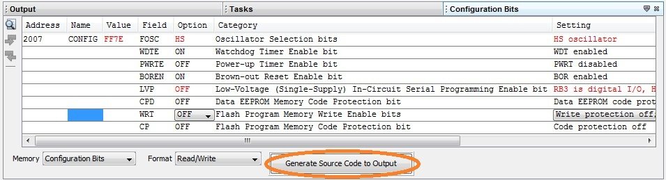
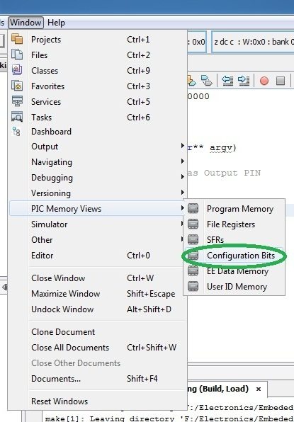
Go to Window >> PIC Memory Views >> Configuration Bits
- You can select the configuration at the bottom of the IDE as shown below
- Click Generate Source Code to Output

- You can simple copy paste this generated code to code editor.
- Then enter the remaining code for the blinking of LED.
- Build the Project
- Hex File will be generated in the location Your Project Folder >> dist >> default >> production
No comments:
Post a Comment